If you hover over an element of the plug-in suite with your mouse, you will see a short explanation and practical tips in the lower left corner, so that you can start exploring these plug-ins right away.
Full Preset Names will also be displayed here when you hover over a preset name in the Preset Browser.
All plug-ins share some operational features. Here’s a description of these common controls:
Ctrl + Click (Windows), Command + Click (macOS) resets the selected control to its default value. Pressing Shift while dragging a control increases its resolution for fine-tuning adjustments. Double-clicking on a control allows you to enter a numerical value using the computer keyboard.
Important
Plug-ins are only guaranteed to work at a host sampling rate of 44,100 Hz and higher. If the rate is set to, e.g., 22,050 or 33,000 Hz, plug-ins may perform improperly or in a limited way.
The Factory Presets option lets you select one of the pre-configured settings for the plug-in, many of which are specifically adapted for Vienna Instruments (especially in Equalizer Pro and Compressor Pro ). You can Load and Save your User Presets on your computer and exchange them with other users of Vienna Suite. Make sure to back up your custom user presets regularly – you don’t want to lose them … The default path for the Preset Folder is:
Windows:
%appdata%/VSL/[PluginName]/PresetsmacOS:
[Macintosh HD]/Users/[YourName]/Library/Application Support/VSL/[PluginName]/Presets
[Macintosh HD] is the name of the hard disk the operating system is installed on. Please note that on Macs the User Library folder is hidden by default. You may un-hide it by using the Finder menu command View>Show View Options, selecting the option "Show Library Folder".
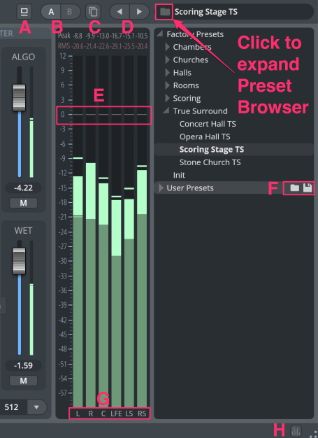
Toggle Bypass (A): Bypasses plug-in.
A/B (B): Provides quick-store of settings, to compare two different settings comfortably.
Copy State Button (C): Copies current state to the inactive A/B state.
Arrows (D): Use the arrows above the browser to step through the presets.
Folder Button: Opens the Preset Browser.
Factory Presets: Display all available Factory Presets in the browser window below.
User Presets (F): Manage your customized presets. Click the folder icon to create a new folder. The disk icon will save your preset.
Right-click presets: Lets you assign the selected preset as the default (startup) preset. With user presets you can also choose to delete or overwrite the preset.
TIP: Some of the factory preset names are longer than the Preset Browser can display. Hover over the preset name with your mouse to see the full name in the lower left corner of the plug-in interface!
Output Meter (E): Shows the levels of all output channels. Clicking on the numerical peak displays above the meters resets the peak values.
Output Gain (E): The white level markers work as sliders and let you adjust the volume of the processed signal for each channel individually. Alt/Option + drag adjusts all sliders. Ctrl/Cmd + click resets the level.
Show / Hide Meters (H) switches output meter visibility to gain more space for the main processing elements. You can SOLO channels separately by clicking on the channel names below the meters (G). Solo channels will be displayed in red.
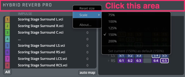
Click on the plug-in name to scale the size of each plug-in window and set the current state as default for the selected plug-in 25% steps from 75% to 200%. Different scale settings scale all elements of a plug-in. Additionally, you can always resize the window with the mouse by dragging the borders of a plug-in. You can also Reset size and access the "About" details here.
Assign your available channels to different groups for separate processing options.
In Analyzer Pro, Equalizer Pro, and Compressor Pro you can process up to 8 individual channels or groups separately in one plug-in. With Limiter Pro and Multiband Pro, several channels of a multi-channel signal may be grouped for linked processing, with up to 8 possible groups!
Always convenient: This spectrum analyzer comes with a fast and accurate display that lets you zoom right into the frequency spectrum and a note display that locates the loudest-sounding frequency in your input signal. It supplies two different modes: an analog constant-q mode with 120 frequency bands, and a powerful digital FFT analyzer.

Analyzer Pro offers 8 groups. Each group represents an analyzer graph, and any of the 8 groups may be displayed at any time (also simultaneously) by clicking the colored group number to the left of the group matrix.
By default, all channels are assigned to Group 1, and only this group is displayed.
By assigning different channels to different groups, you can visualize each channel individually. Each channel pair (L/R, Ls/Rs, etc.) also offers a M/S encoding button, which allows for analysis of Mid and Side channels.

Frequency Display: Shows the frequency range. Click-drag to zoom in, right-click to reset zoom.
PRECISION: Filter Quality Factor. Sets the steepness of the analyzed filter bands. Increasing precision will yield a more accurate readout of frequencies, but also a slower response time.
REFERENCE: Analog Analyzer Reference Pitch.
STYLE: Drawing Style. Select how the frequency spectrum should be displayed; choose between Bars and Graph.
NOTE: When active, the note value of the loudest frequency is shown in the frequency display.

Frequency Display: Shows the frequency range. Click-drag to zoom in, right-click to reset zoom.
SIZE: Sets the FFT window size. Larger window sizes will give more accurate readings for bass frequencies but will slow down the analyzer’s update rate.
OVERLAP: Sets the FFT window overlap. A higher overlap will help to increase the update rate for larger window sizes but can increase CPU usage.
TYPE: Sets the FFT window type. The default option (Hann) is optimal for most musical analyses. Background information: https://en.wikipedia.org/wiki/Window_function

WEIGHTING: Spectral Weighting Filter. A, B, and C curves are available to simulate human hearing (see diagram to the right). The default option is OFF.
SLOPE: Spectral Slope. Settings: 0 db, 1.5 dB, 3 dB, 4.5 dB, 6 dB. The default option (3 dB) will display pink noise as flat, while the 0 dB option will display white noise as flat.
HOLD: Holds the peaks of all frequency bands.
FALLOFF: Choose between Linear and Newton (which emulates the gravity on this planet).
ATT: Sets the attack time of the analyzer (0–1000 ms).
REL: Sets the release time of the analyzer (0–1000 ms).
Compressor Pro lowers the level of the input when it exceeds the threshold. The amount of attenuation is determined by the Attenuation / Ratio and input level. When the input level goes above the threshold, attenuation is added gradually to reduce distortion.
The compressor’s attack time determines how fast the compression is applied – this way you can sculpt the attack of your instruments, making them softer or more aggressive.
The release time determines the time it takes the compressor to decrease the applied gain reduction. Depending on the length of the release time you can minimize the "sonic body" of an instrument in comparison to the attack sound, or you can apply extremely short release times to emphasize it.
Usually, the incoming signal is identical to the input to the gain reduction stage. Compressor Pro can shape the controlling signal (aka "Sidechain") to allow for even more musical compression modes. You may combine external sidechain (VST3, AU, AAX formats only) with any available input channel to form your sidechain input for a particular group. We have included Factory Presets for many instruments contained in the wide array of Vienna Instruments Collections, making it very comfortable to start your mixing session.
The Instrument Presets have been converted from the original Vienna Suite Instrument Presets.

Compressor Pro offers 8 control groups. By assigning a channel to a control group, Compressor Pro will only use the sidechain inputs selected for that particular group when applying compression.
This way, you can create very advanced setups to shape any surround signal.
In order to set up stereo M/S processing for Compressor Pro, enable the [M/S] button for L/R channels, and then use a different group for each channel. Compressor settings can thus be entirely separated for M/S channels.
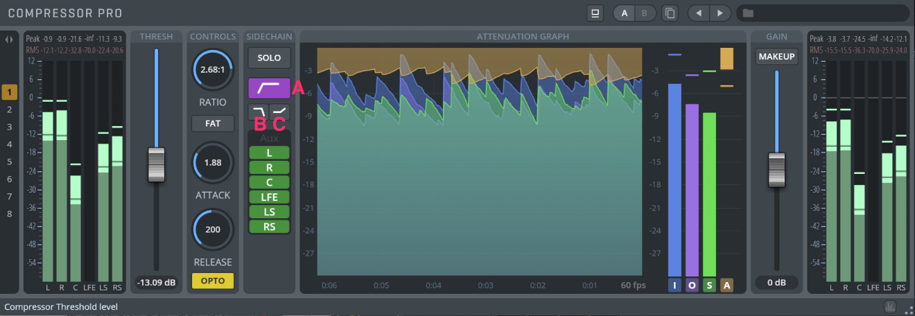
THRESH: The level above which the signal is reduced. A low threshold means that a larger portion of the signal will be processed.
CONTROLS Window
RATIO: Determines the input/output ratio for signals above the threshold. For example, a 3:1 ratio means that a signal overshooting the threshold by 3 dB will leave the compressor 1 dB above the threshold. Range: 1:1 to 20:1.
FAT: Activates a process that makes the signal sound "thicker", similar to tape compression. When FAT mode is on, the sound is hard-clipped at 0 dB. With a certain configuration (when the signal may exceed 0 dB), this may cause distortion in the attack segment. In this case, please switch off make-up gain or turn off FAT mode.
ATTACK: Sets the time the compressor needs to increase gain reduction to reach the level determined by a ratio (0.2–500 ms).
RELEASE: The ‘release phase’ is the period when the compressor decreases gain reduction to the level determined by threshold and ratio (or to zero, once the level has fallen below the threshold). Values: 10–5000 ms.
OPTO: Activates optical release simulation, resulting in a more "breathing" sound. Compared with the same settings without Opto Mode, a little less compression will be applied to the signal.
SIDECHAIN Window
The sidechain works exclusively with the internal sidechain filter. Sidechain settings only affect the compressor’s controls, NOT the signal itself!
In other words: sidechain input is used to calculate the gain curve applied to the signal.
SOLO: Solos the sidechain signal.
LOW CUT FILTER (A): Use low cut (120 Hz at 12 dB/oct) when the signal starts to "pump" due to high energy in the lower frequencies.
HIGH CUT FILTER (B): Use high cut (4 kHz at 12 dB/oct) when the signal's attacks begin to sound lifeless and flat, especially when using fast attack times.
HIGH SHELF FILTER (C): Use high shelf (+6dB at 4 kHz) when you want to get rid of excessive high-frequency content, e.g., voices with strong "sss" and "shhhh" sounds.
SIDECHAIN INPUT selection: Choose the sidechain input from any available channel.
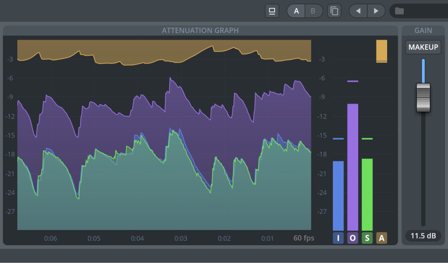
ATTENUATION GRAPH Display: Shows the input and output signals in real time.
I: Show the input graph.
O: Show output graph.
S: Show the sidechain graph.
A: Show attenuation graph.
GAIN SLIDER: Determines the signal’s output volume.
MAKEUP: Automatically compensates for the gain loss in the compressed signal based on the current threshold, ratio, and attack settings.
Equalizer Pro operates like a standard EQ filter, but it is powered by highly sophisticated 64-bit processing algorithms. The filter response display provides comprehensive control and visual feedback of the EQ curve being applied. Eight fully parametric bands of EQ are completed with an integrated 120-band spectrum analyzer.
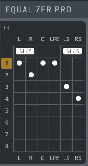
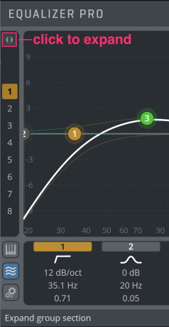
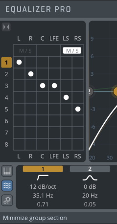
Group section The group section inside the Equalizer Pro plug-in allows for powerful linking of channels. Each channel is assigned to one of the 8 groups (or none, to bypass the channel). Clicking on a group number brings up the settings for this group in the main window.
M/S processing is available for each channel pair (L/R, Ls/Rs, etc.). Activating the M/S button for a channel pair M/S-encodes the channels before processing, and M/S-decodes the channels after processing, enabling individual equalization of Mid/Side channels.
We have included Factory Presets for many instruments contained in the wide array of Vienna Instruments Collections, making it very comfortable to start your mixing session. These Instrument Presets were converted from the original Vienna Suite Instrument Presets.
The Factory Presets are subdivided into so-called "Resonance Menu" Presets and "Character" Presets.
In the Resonance Menus, up to 5 frequencies were localized for the respective instrument/ensemble which could be problematic in the mix. Simply activate the desired EQ filter band’s preset parameters by clicking on it; now you can determine whether the disturbing resonances of this instrument get filtered out. Also, try combinations of several bands, and reduce or increase the attenuation as needed. The idea is to get a better placement of the original, pure sound of the Vienna Instruments in a complex mix without larger adjustments.
Character Presets carve out an instrument’s or ensemble’s manifold sound possibilities. Here, the pure sound of a Vienna Instrument is deliberately altered in different directions. These Presets multiply the sounds of your Vienna Instruments Collection – a true fountain of inspiration!
Filter Response Display: Shows the response curve and frequency analysis for the current settings. The (horizontal) frequency range is from 20 Hz to 20 KHz, the (vertical) amplitude scale is in dB, adjustable between 6 and 36 dB. A right-click in the Filter Response Display lets you copy, paste, and reset a group from the context menu.
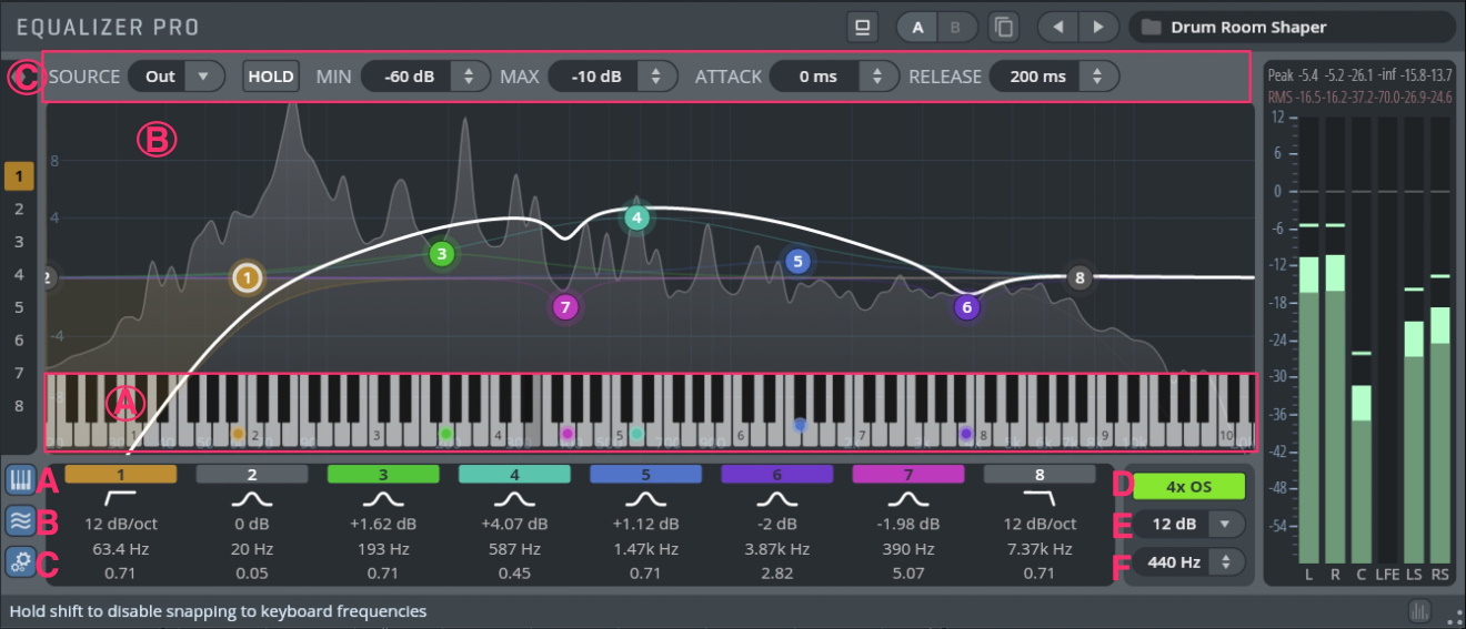
Show / Hide Keyboard (A):
Click-drag the keyboard to locate frequencies using a sine tone. Drag the mouse up/down to adjust the volume of the tone. Hold
Shiftto disable quantizing to keyboard frequencies.Click-drag an equalizer node on the keyboard to play back a sine tone while simultaneously adjusting the frequency of this node. Hold
Shiftto disable quantizing to keyboard frequencies.Double-click a keyboard equalizer node to pull out this frequency (creates a 6dB peak filter with Q=15 at this frequency).
If HOLD is activated for the Analyzer, the volume of the keyboard will be adapted to the hold curve’s level of the current frequency.
Show / Hide Analyzer (B): Enable/disable a 120-band spectrum analyzer for the selected group. The analyzer only draws CPU cycles while the GUI is shown.
Show / Hide Analyzer Settings (C): Adjust the settings in the display.
SOURCE: Choose between Input and Output signal to be displayed (pre/post EQ).
HOLD: Holds the peaks of all frequency bands.
MIN: Real-time Analyzer minimum level (-180 dB to 20 dB)
MAX: Real-time Analyzer maximum level (-180 dB to 20 dB)
ATTACK: Sets the attack time of the analyzer (0–1000 ms).
RELEASE: Sets the release time of the analyzer (0–1000 ms).
4x OS (D): Enable 4 times oversampling mode for the equalizer process.
dB Scale (E): Lets you specify the vertical scale (dB) of the filter response display in 6 dB steps (6, 12, 18, 24, 30, 36 dB). By dragging an equalizer node outside the range of the current scale, the scale will adjust automatically.
Reference Pitch (F): Sets the A4 reference frequency for the keyboard and analyzer.
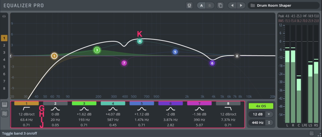
EQ Filter Bands (G): The eight bands of the EQ that can be independently enabled and programmed. The numbers and colors of the EQ Filters correspond to the numbers and colors of the filter handles in the Filter Response Display. Click the colored filter band buttons to enable/disable the corresponding filter.
Available Filter types: Peak, High Shelf, Low Shelf, High Cut, Low Cut, Notch, and Bandpass.
Gain (H): Adjusts the peak gain of the corresponding filter in a range from –36 dB to +36 dB. In place of gain, High/Low Cut, Notch, and Bandpass filters offer 6 filter slopes (6, 12, 24, 36, 48, 60 dB/oct).
Frequency (I): Sets the center frequency.
Quality(J): Adjusts the filter width of the corresponding filter band from 0.05 to 20. Use the mouse wheel to adjust the Q setting for the currently selected filter(s).
Filter handle (K): Drag this handle to graphically adjust the filter’s boost/cut and/or frequency. When adjusting the filter handle, Shift increases precision, while Option / Alt locks the frequency. Cmd / Ctrl -clicking a handle resets the band to the default settings. Holding Shift or using the lasso also lets you select multiple filter handles.
Solo mode: Cmd/Ctrl+Option/Alt+ drag on a filter handle to enter solo mode, which allows you to find your problem frequencies with higher accuracy. Dragging up/down will increase the level of the soloed band.
Composite Curve: Shows the overall response curve of the current settings in the Filter Response Display. The active group’s curve is displayed in white. Other groups (with active channel assignments) will be displayed in the background, in their respective colors. You can double-click a filter curve of other groups in the background to switch to other groups immediately.
Individual Filter Curve: Each individual filter’s response curve is displayed in the filter’s color when selected.
If you are looking for that "glowing" sound, Exciter Pro will create higher-order harmonics from the fundamental frequency signals present in the recording which do just that. Processed with 4 x oversampling and unique distortion algorithms to completely eliminate aliasing, the result can be monitored with a high-frequency FFT spectrum analyzer.

DRIVE: Sets the distortion level of the harmonics added by Exciter Pro.
FREQUENCY: Adjust the cutoff frequency for Exciter Pro to take effect. The signal part below the chosen cutoff frequency will not be altered. COLOR: Changes the musical coloration of the signal between even and odd harmonics. Setting the slide to 100% will only add odd harmonics, whereas 0% will only add even harmonics to your signal.
AMOUNT: Adjusts the mix between the unprocessed signal and the generated harmonics/overtones. This acts like a "send" channel: 0% equals the original signal, and 100% adds the maximum of the processed signal.
Vienna Suite Limiter Pro maximizes the apparent volume within the available dynamic range by reducing the distance between average program levels and their associated peaks. Just the right amount of maximization will make your signal seem loud without ever exceeding the available dynamic range, whereas too much limiting will make your signal sound "flat" and unnatural.
Processing at 64-bit floating point resolution, which provides the highest fidelity with no added noise, the comfort of a real-time input/output waveform display combined with an auto-mode for transparent maximization makes it very intuitive to operate.
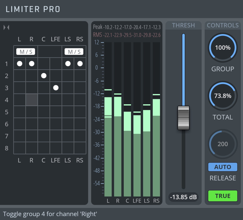
Limiter Pro allows for fine-grained control over the linking between audio channels. A stereo limiter usually has its channels linked, so as not to shift its panorama when peaks occur in only one of the two channels. Surround limiting has different requirements since limiting all channels in the same way as done in a stereo limiter would sound unnatural. Limiter Pro offers a group section, allowing you to link the attenuation of channels into groups.
To recreate the operation of a stereo compressor, one could thus set both input channels to the same group, and then adjust the GROUP value to 100% to achieve full linkage in the attenuation of both channels.
For surround purposes, it can be beneficial to link speaker pairs. In a 5.1 setup, you would set L/R and Ls/Rs each to individual groups, and then adjust the GROUP knob to achieve the desired result.
The TOTAL knob acts as an additional group into which all channels are fed. Combining GROUP linking for speaker pairs and TOTAL linking allows you to adjust limiting for any surround format.
M/S processing is available for each channel pair (L/R, Ls/Rs, etc.). Activating the M/S button for a channel pair M/S-encodes the channels before processing, and M/S-decodes them again after processing.
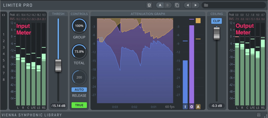
Input Meter: Shows the levels of all available input channels. Clicking on the numerical peak displays above the meters resets the respective peak values.
THRESH: Threshold sets the point at which the limiter starts to affect the input signal. Lowering the threshold setting has the effect of raising the output gain of the signal. The average level of the signal is increased while the limiter assures that the signal will not exceed the ceiling level.
GROUP: Group link. Controls the extent to which channel compression affects other channels within the same group. Assign and select groups in the group section window.
TOTAL: Total link. Controls the extent to which channel compression will be globally linked between all groups.
RELEASE TIME: Controls how long it takes for the limiter to recover from attenuating the signal after it has dropped below the threshold. Values: 10–5000 ms.
AUTO RELEASE: Enables/disables the manual release slider and lets the limiter control release time depending on the input signal, resulting in the most transparent limiting possible.
TRUE: Enables True Peak envelope detection – a 16x oversampled detector for more accurate limiting.
ATTENUATION GRAPH Window: Shows the current input (I) and output (O) signals, the applied attenuation (A) as well as the attenuation graph. Each signal can be switched on and off individually with the buttons to the right (I/O/A). If you need to reduce CPU load, you can reduce the update rate of the attenuation graph (1–240 frames per second).
CEILING: Sets the maximum output of Limiter Pro.
CLIP: Always clips the output level to 0 dBFS.
The Matrix Mixer Pro features a gain, delay, and phase network which allows you to solve a variety of problems, for example:
Feeding Left/Right channel into LFE channel
Phase adjustment of a single channel in a surround setup
Delay individual channels in a surround setup
Solving phase problems of individual channels
In Gain Mode, the matrix displays gain settings for each source-destination channel feed.
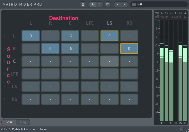
Gain adjustment: Adjust gain for each feed by click-dragging on the node. Double-click on a node to enter a value from the keyboard. Values: infinite to 12 dB.
Phase reverse: By right-clicking on a node, this node will be phase reversed. Nodes with active phase reversal are marked by an orange ring. You may, for instance, send a phase-reversed feed from the left channel to the right surround channel, and a phase-reversed feed from the right channel to the left surround channel in order to create certain effects, or "pseudo-surround". In Delay Mode, each node displays a delay for the individual feed. The delay mode allows you to set an individual delay for each matrix node, enabling very complex mixing.
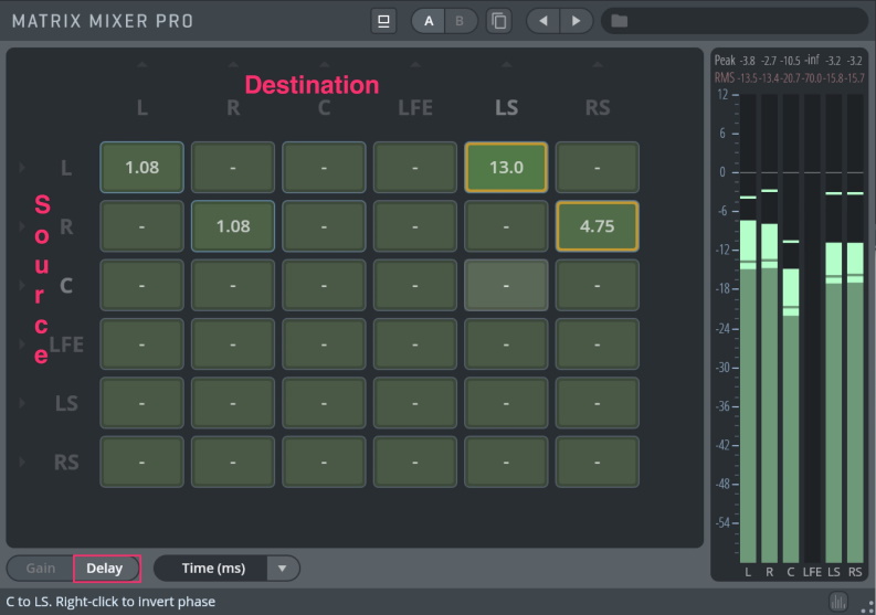
Delay adjustment: Adjust the delay time for each feed by click-dragging on the node. Double-click on a node to enter a value from the keyboard.
Delay mode: Choose to display delay values by Time (ms), Distance (m), or Samples.
Switching back to Gain mode after applying delay settings to a node will show a green frame around the affected node, signifying an active delay value.
Phase reverse: As in Gain mode, right-clicking on a node will phase-reverse it. Nodes with active phase reversal are marked by an orange ring.
This is a specialized plug-in for balancing your mixes within any surround format.

Drag the dot to achieve balancing/panning between the available speakers. Hold Shift to only alter the dot’s angle. Hold Ctrl/Cmd to reset the dot. Additionally, each speaker can be enabled/disabled by clicking its icon on the circle.
CENTER: Controls the level of the Center channel (if available).
CENTER LINK ICON: When enabled, include the Center channel in balancing/panning.
LFE: Controls the level of the LFE channel (if available).
RANGE: Controls the dB range of the jellyfish level meter.
FALLOFF: Controls the falloff time of the jellyfish level meter.
ANGLE: Balance angle.
RADIUS: Balance radius.
SPREAD: Controls the spread of balancing/panning between speakers.
PAN LAW: Determines how the signal level is affected by panning. Without compensation, the combined loudness of the left and the right signals will be higher if a channel is panned to the center than if it is panned to one side. The Pan Law allows for attenuation of the signal when it is panned to the center. The optimum value of this parameter depends a lot on the input source. Adjustable from 0 to 6 dB (0 dB actually turns off constant power panning).
A brilliant tool for panning your sources from mono/stereo to any surround format.

Drag the dots to achieve balancing/panning between the available speakers. Hold Shift to only alter a dot's angle. Hold Ctrl/Cmd to reset the dots. Additionally, each speaker can be enabled/disabled by clicking its icon on the circle.
CENTER: Controls the level of the Center channel (if available).
CENTER LINK ICON: When enabled, includes the Center channel in balancing/panning.
LFE: Controls the level of the LFE channel (if available).
RANGE: Controls the dB range of the jellyfish level meter.
FALLOFF: Controls the falloff time of the jellyfish level meter.
ANGLE: Balance angle.
RADIUS: Balance radius.
SPREAD: Controls the spread of balancing/panning between speakers.
PAN LAW: Determines how the signal level is affected by panning. Without compensation, the combined loudness of the left and the right signal will be higher if a channel is panned to the center than if it is panned to one side. The Pan Law allows for attenuation of the signal when it is panned to the center. The optimum value of this parameter depends a lot on the input source. Adjustable from 0 to 6 dB (0 dB actually turns off constant power panning).
On this page
- Mouse-Over Descriptions
- Operational Features
- Preset Management
- Output Section
- Scaling Options
- Group Section (for selected plug-ins)
- Analyzer Pro
- Group section
- MODE: Analog Mode
- MODE: Digital Mode
- Compressor Pro
- Group section
- Equalizer Pro
- Exciter Pro
- Limiter Pro
- Group Section
- Matrix Mixer Pro
- Surround Balance Pro
- Surround Pan Pro